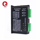
M545D 2 phase Microstep stepper motor driver
Features
1. 2phase stepper driver, adoption of bipolar constant-current chopper technology
2. Low-noise, low-vibration and low temperature rising
3. Voltage 24-50VDC
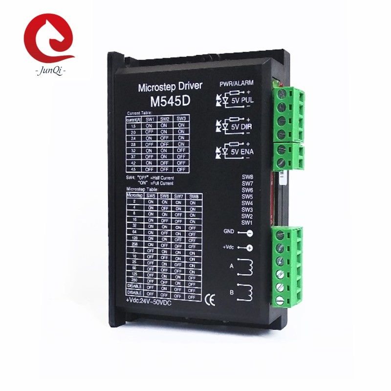
4. With 8 stalls output current setting, current range 1.5-4.5A
5. With 14 stalls microstep subdivision setting
6. Automatic Half current, motor wires misconnected, over voltage, under voltage, over current protection
7. Internal optical isolation, highest frequency response 200KHZ
8. Suitable for nema 23, nema 34 stepper motor current under 4.5A
Current Selection:
| Peak |
RMS |
SW1 |
SW2 |
SW3 |
| 1.5A |
1.07A |
on |
on |
on |
| 2.0A |
1.43A |
off |
on |
on |
| 2.4A |
1.72A |
on |
off |
on |
| 2.8A |
2.00A |
off |
off |
on |
| 3.2A |
2.28A |
on |
on |
off |
| 3.7A |
2.64A |
off |
on |
off |
| 4.2A |
3.00A |
on |
off |
off |
| 4.5A |
3.21A |
off |
off |
off |
Microstep Selection:
| Pulse/Rev |
SW5 |
SW6 |
SW7 |
SW8 |
| 400 |
on |
on |
on |
on |
| 800 |
on |
off |
on |
on |
| 1600 |
on |
on |
off |
on |
| 3200 |
on |
off |
off |
on |
| 6400 |
on |
on |
on |
off |
| 12800 |
on |
off |
on |
off |
| 25600 |
on |
on |
off |
off |
| 51200 |
on |
off |
off |
off |
| 1000 |
off |
on |
on |
on |
| 2000 |
off |
off |
on |
on |
| 5000 |
off |
on |
off |
on |
| 10000 |
off |
off |
off |
on |
| 25000 |
off |
on |
on |
off |
| 50000 |
off |
off |
on |
off |
Driver Functions Descriptions:
| Driver function |
Operating instructions |
| Output current setting |
Users can set the driver output current by SW1-SW3 three switches.
The setting of the specific output current, please refer to the instructions of the driver panel figure.
|
|
Microstep setting
|
Users can set the driver Microstep by the SW5-SW8 four switches.
The setting of the specific Microstep subdivision, please refer to the instructions of the driver panel figure.
|
|
Automatic half current function
|
Users can set the driver half flow function by SW4. "OFF" indicates the quiescent current is set to half of the dynamic current, that is to say, 0.5 seconds after the cessation of the pulse, current reduce to about half automatically. "ON" indicates the quiescent current and the dynamic current are the same. User can set SW4 to "OFF", in order to reduce motor and driver heating and improve reliability. |
|
Signal interfaces
|
PUL+ and PUL- are the positive and negative side of control pulse signal; DIR+ and DIR- are the positive and negative side of direction signal; ENA+ and ENA- are the positive and negative side of enable signal. |
|
Motor interfaces
|
A+ and A- are connected to a phase winding of motor; B+ and B- are connected to another phase winding of motor. If you need to backward, one of the phase windings can be reversed. |
|
Power interfaces
|
It uses DC power supply. Recommended operating voltage is 24VDC-50VDC, and power consumption should be greater than 100W. |
|
Indicator lights
|
There are two indicator lights. Power indicator is green. When the driver power on, the green light will always be lit. Fault indicator is red, when there is over-voltage or over-current fault, the red light will always be lit; after the driver fault is cleared, if re-power the red light will be off. |
|
Installation instructions
|
Driver dimensions:118×75×32mm, please refer to dimensions diagram. Please leave 10CM space for heat dissipation. During installation, it should be close to the metal cabinet for heat dissipation. |
Signal Inter face details:
The internal inter face circuits of the driver are isolated by the opt coupler signals,
R in the figure is an external current limiting resistor. The connection is differential.
And it has a good anti-Jamming performance.

Control Signal and external interface.
| Phenomenon |
Reason |
Solution |
|
The red indicator is on.
|
1.A short circuit of motor wires. |
Inspect or change wires |
| 2.The external voltage is over or lower than the driver’s working voltage. |
Adjust the voltage to a reasonable rang |
| 3.Unknown reason |
Return the goods |
Mechanical Dimension(mm):
Packing:
Cardboard boxes plus foam packaging. We can also pack the goods according to customer's requirements.
Certificate:
Transportation:
At present, our company supports a variety of modes of transport, or according to customer's needs to choose the mode of transportation.
FAQ:
1.Q: Can I get some samples first?
A: Sure, we are honored to offer you samples for your check.
2.Q: Do you have the products in stock?
A: Our products are manufactured according to your order except the normal products.
3.Q: What's the delivery time?
A: It usually takes about 7 working days,but the exact delivery time might be different for different order or at different time.
4.Q: How does your factory do regarding quality control?
A: Quality is priority. We always attach great importance to quality control from the beginning to the end of the production. Every product will be fully assembled and carefully tested before packed

 Your message must be between 20-3,000 characters!