Place of Origin: | China |
Brand Name: | JEUNKEI |
Certification: | ISO9001,CE |
Model Number: | JY213L |
Minimum Order Quantity: | 50pcs ( sample available) |
---|---|
Price: | USD0.5-USD1/PC |
Packaging Details: | Suite for export |
Delivery Time: | depend on the order quantity /Negotiable |
Payment Terms: | T/T, , Western Union, Paypal |
Supply Ability: | 1000pcs per day |
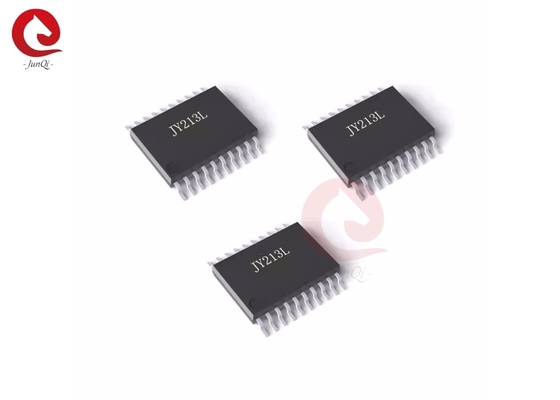
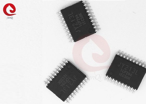
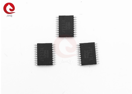
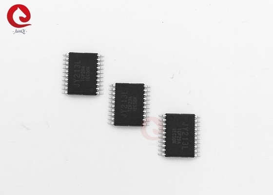
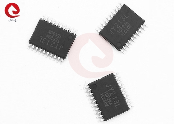
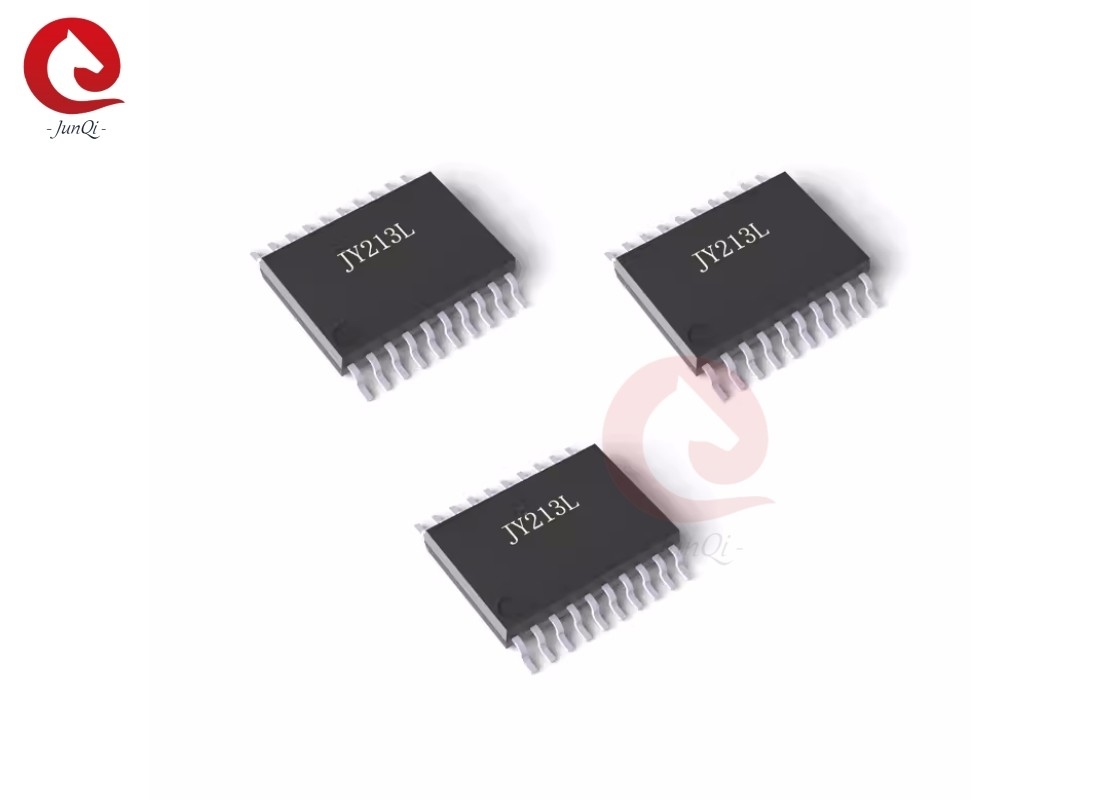
Name: | 90V Three-Phase Gate Driver | Model No.: | JY213L |
---|---|---|---|
Input Logic Compatible: | 3.3V And 5V | IO+/IO-: | +1.2A/-2.0A At VCC=15V,VBS=15V |
Operating Temperature Range: | 40℃~125℃ | Small Footprint Package: | TSSOP20L/24L,173mil |
Color: | Black | Application: | General Purpose Inverter |
High Light: | A9065451513 Universal Power Window Switches,A9065451513,4Pin Universal Power Window Switches |
Description:
The JY213L is a high-speed 3-phase gate driver for power MOSFET and IGBT devices with three independent high and low side referenced output channels. Built-in dead time protection and shoot-through protection prevent damage to the half-bridge. The UVLO circuits prevent malfunction when VCC and VBS are lower than the specified threshold voltage. A novel high-voltage BCD process and common-mode noise canceling technique provide stable operation of high-side drivers under high dV/dt noise conditions while achieving excellent negative transient voltage tolerance. An enable pin (EN) is included so that standby mode may be used to set the chip into a low quiescent current state to realize long battery lifetime.
Features:
• Integrated 90V half-bridge high side driver
• Ability to drive up to 3-phase half-bridge gates
• Built-in boot strap diode for each high side channel
• Built-in dead time protection
• Shoot-through protection
• Under voltage lockout for VCC and VBS
• Low operation voltage 0–5.5V for VCC and VBS
• 3.3V and 5V input logic compatible
• Enable pin (EN) for low standby current
• IO+/IO-: +1.2A/–2.0A at VCC=15V, VBS=15V
• Built-in dead time
• Common-mode dV/dt noise cancellation circuit
• Tolerant of negative transient voltage
• Low dI/dt gate drive for better noise immunity
• –40ºC to 125ºC operating range
• Small footprint package
Applications:
• E-BIKE/electric power tool 3-phase motor driver
• Battery-powered mini/micro motor control
• General purpose inverter
Block Diagram:
Typical Application Circuit:
PIN Configuration:
PIN Descripition:
Pin Name | Description | Pin No. | |
TSSOP20L | TSSOP24L | ||
HIN1 | Logic input for phase-1 high-side gate driver | 1 | 1 |
HIN2 | Logic input for phase-2 high-side gate driver | 2 | 2 |
HIN3 | Logic input for phase-3 high-side gate driver | 3 | 3 |
LIN1 | Logic input for phase-3 low-side gate driver | 4 | 4 |
LIN2 | Logic input for phase-3 low-side gate driver | 5 | 5 |
LIN3 | Logic input for phase-3 low-side gate driver | 6 | 6 |
EN | Logic input for standby mode control | - | 7 |
VCC | Logic and low-side gate drivers power supply voltage | 7 | 8 |
COM | Logic ground and low-side gate drivers ground | 8 | 9 |
LO3 | Phase-3 low-side gate driver output | 9 | 10 |
LO2 | Phase-2 low-side gate driver output | 10 | 11 |
LO1 | Phase-1 low-side gate driver output | 11 | 12 |
NC. | - | 13 | |
VS3 | Phase-3 high-side driver floating supply offset voltage | 12 | 14 |
HO3 | Phase-3 high-side driver output | 13 | 15 |
VB3 | Phase-3 high-side driver floating supply | 14 | 16 |
NC. | Not connected | - | 17 |
VS2 | Phase-2 high-side driver floating supply offset voltage | 15 | 18 |
HO2 | Phase-2 high-side driver output | 16 | 19 |
VB2 | Phase-2 high-side driver floating supply | 17 | 20 |
NC. | Not connected | - | 21 |
VS1 | Phase-1 high-side driver floating supply offset voltage | 18 | 22 |
HO1 | Phase-1 high-side driver output | 19 | 23 |
VB1 | Phase-1 high-side driver floating supply | 20 | 24 |
Package Information:
For More products information details, please contact with us via email: ivanzhu@junqitrading.com
Contact Person: Ivanzhu
Tel: 0086-13961407941